Режим работы пункта самовывоза:
Пн-пт 10:00-21:00, сб-вс 10:00-19:00.
Колл-центр работает с 10 до 18 по будням.


- Описание
- Характеристики
- Аналоги
- Отзывы (0)
Модель снята с производства. Аналоги по ссылкам:
Полётные контроллеры F4
Полётный контроллер Matek F405-HDTE
Полётный контроллер Holybro Kakute H7
Полётный контроллер Matek H7A3-SLIM
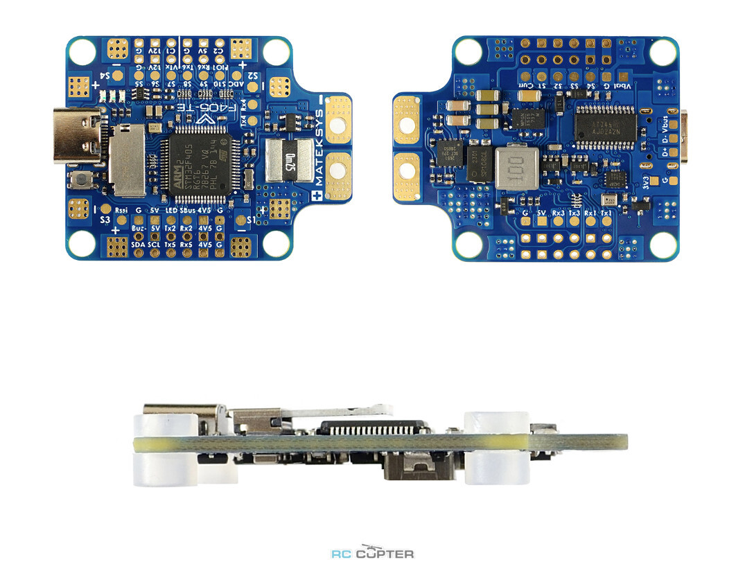
Полетный контроллер F405-TE компании Mateksys
(STM32F405RGT6, ICM42688P, SPL06, OSD, SD slot, 6x UARTs, 1x I2C, 11x PWM outputs)
- F405-TE has INAV fw preloaded for QC
- set BLHeli32 ESC PWM rate to 48KHz or higher in BLHeliSuite
- ArduPilot fw, “Internal errors 0x4000 l:213 spi_fail” warining, pls set LOG_BACKEND_TYPE = 1 (File) for SD card logging.
- Download ArduPilot firmware from HERE.
- With INAV firmware, DSHOT can not work on S3, S5,S7 because of DMA clash, pls use ONESHOT or MULTISHOT and calibrate ESC PWM range.
- Download INAV firmware 4.1.x from our website. INAV5.x or newer directly from INAV configurator
- If using 5V passive buzzer, CLI “set beeper_frequency = 2500”
- MATEKF405TE_SD target was supported since BF4.4.
- set dshot_bitbang = ON when using X6 and X8 DSHOT,
- You may download BF 4.3 directly from BF configurator, BF 4.2.x from our website (click “Firmwares” button at upper right corner)
- Barometer SPL06-001 is not supported by Betaflight.
INAV, DSHOT can not work on S3, S5,S7 because of DMA clash, pls use ONESHOT or MULTISHOT and calibrate ESC PWM range.
BetaFlight, set dshot_bitbang = ON when using X6 and X8 DSHOT.
BetaFlight, Target name was renamed as MatekF405TE_SD
ArduPilot, set LOG_BACKEND_TYPE = 1 (File) for SD card logging
- MCU: 168MHz STM32F405RGT6
- IMU: ICM42688-P (SPI)
- Baro: SPL06-001 (I2C)
- OSD: AT7456E (SPI)
- Blackbox: MicroSD slot (SPI)
- 6x UARTs, 1x Softserial_Tx option(INAV/BF)
- 11x PWM outputs (8x Dshot compatible with BF/ArduPilot)
- 1x I2C
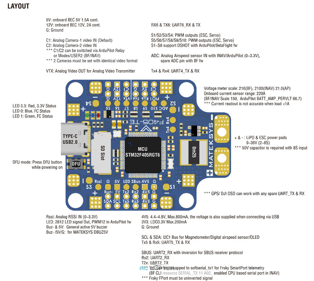
- 4x ADC (VBAT, Current, RSSI, Airspeed)
- 1x spare PINIO
- 4x individual ESC power/signal pads
- 1x Group of G/S1/S2/S3/S4 pads for 4in1 ESC Signal/GND
- Built in inverter on UART2-RX for SBUS input
- Switchable Dual Camera Input
- Input: 9~36V (3~8S LiPo)
- PDB: 4x 35A (Max.4x 50A)
- BEC: 5V 1.5A
- BEC: 12V 2A
- LDO 3.3V: 200mA
- Current Senor: 220A, 3.3V ADC (INAV/BF scale 150, ArduPilot 66.7 A/V)
- Battery Voltage divider 1K:20K (INAV scale 2100, BF scale 210, ArduPilot BATT_VOLT_MULT 21.0)
- ArduPilot: MatekF405-TE
- INAV: MATEKF405TE_SD
- BetaFlight: MATEKF405TE_SD
- Mounting: 30.5 x 30.5mm, Φ4mm with Grommets Φ3mm
- Dimensions: 36 x 46 mm
- Weight: 10g
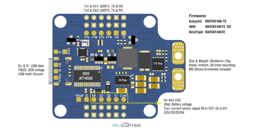
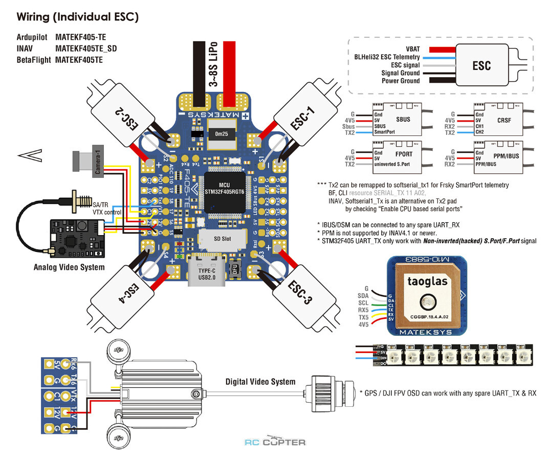
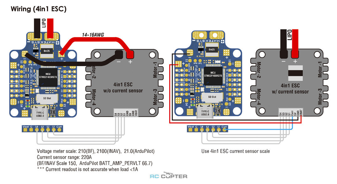
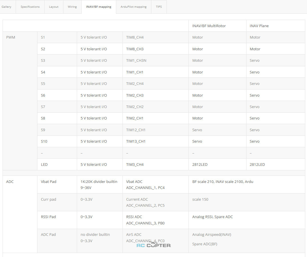
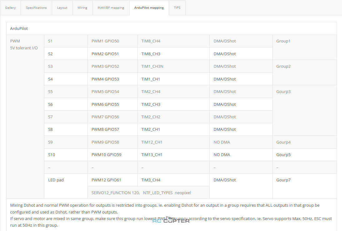
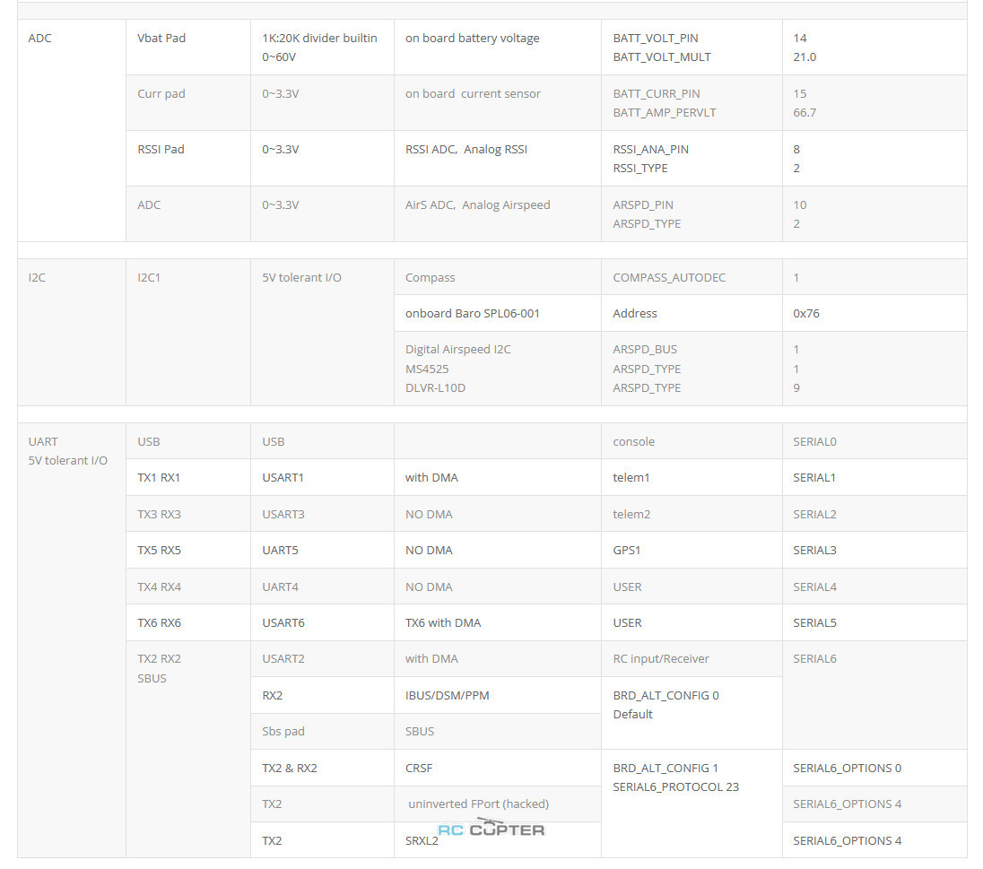
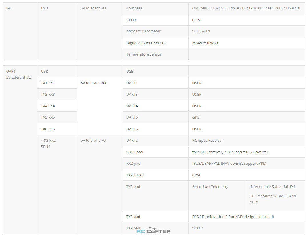
- “Internal errors 0x4000 l:213 spi_fail” warining, pls set LOG_BACKEND_TYPE = 1 (File) for SD card logging.
- If sending highspeed serial data (eg. 921600 baud) to the board, use USART1(Serial1) or USART2(Serial6).
- non-inverted (hacked) S.Port signal
- any spare Uart_TX
- SERIALx_BAUD 57
- SERIALx_OPTIONS 7
- SERIALx_PROTOCOL 4 or 10(for yaapu)
https://ardupilot.org/plane/docs/common-msp-osd-overview.html
- OSD_TYPE = 3
- SERIAL4_PROTOCOL = 33
- MSP_OPTIONS = 0 (polling mode)
- PINIO1, PIO1 pad, Low Level by default
- PINIO2, Camera switch, C1 ON by default
# GPIOs
- PA4 PINIO1 OUTPUT GPIO(81) LOW //PIO1 pad
- PB5 PINIO2 OUTPUT GPIO(82) LOW //camera switch
# RCx_OPTION: RC input option
- 28 Relay On/Off
- 34 Relay2 On/Off
- 35 Relay3 On/Off
- 36 Relay4 On/Off
e.g.
- RELAY_PIN 81 //PIO1 GPIO
- RC7_OPTION 28 //Relay On/Off, Use CH7 of Transmitter to control PIO1 Low/High Level
- RELAY_PIN2 82 //Camera switch GPIO
- RC8_OPTION 34 //Relay2 On/Off, Use CH8 of Transmitter to control high/low level on PB5 pad
The configured feature will be triggered when the auxiliary switch’s pwm value becomes higher than 1800. It will be deactivated when the value falls below 1200.
Check the pwm value sent from the transmitter when the switch is high and low using the Mission Planner’s Initial Setup >> Mandatory Hardware >> Radio Calibration screen. If it does not climb higher than 1800 or lower than 1200, it is best to adjust the servo end points in the transmitter.
Сравнительная таблица полётных контроллеров Matek- Полетный контроллер F405-TE - 1 шт.
- Silicon grommets M4 to M3 - 6 шт.
- Rubycon ZLH 35V/470uF (Low ESR) - 1 шт.
| Производитель: | Matek |